Tejgaon, Dhaka-1215, Bangladesh | sales@uniqueintsg.com | +8801815-944073

PLC and PLC Programming Languages: A Complete Guide to Industrial Automation

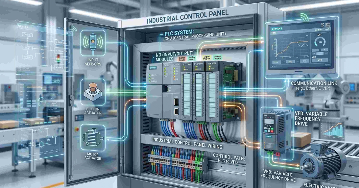
Introduction to PLC and Industrial Automation
Industrial automation has become an essential part of modern manufacturing, helping industries improve productivity, maintain consistent product quality, reduce downtime, and enhance workplace safety. From conveyor systems and packaging machines to steel rolling mills, power plants, and water treatment facilities, automated control systems manage a wide range of industrial operations.
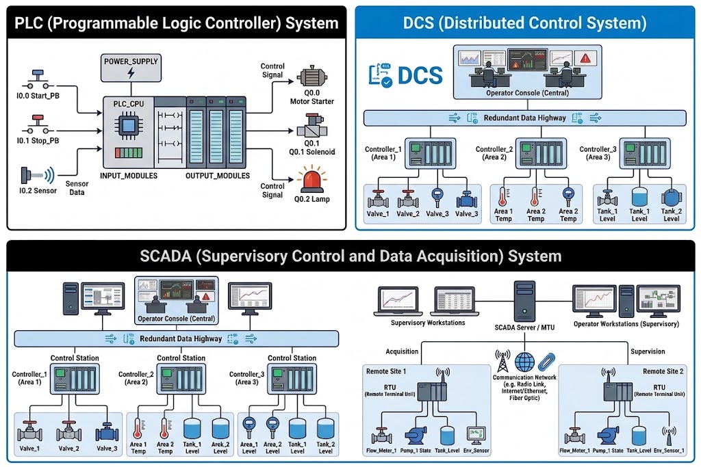
At the heart of many of these systems is the Programmable Logic Controller (PLC). A PLC is an industrial digital controller that monitors input signals, executes a programmed set of instructions, and controls machines and processes according to predefined logic.
PLC programming allows engineers to develop, modify, test, and maintain the logic that controls industrial equipment. Several programming languages are available, including Ladder Diagram (LD), Function Block Diagram (FBD), Structured Text (ST), and Sequential Function Chart (SFC). Each language offers different advantages depending on the application and the engineer’s requirements.
In This Guide
Learn what a PLC is, how it works, its major components, common PLC programming languages, industrial applications, and how to choose the right programming approach for an automation project.
Whether you are an electrical engineer, automation technician, engineering student, or industrial professional, understanding PLCs and their programming languages is a valuable step toward developing practical industrial automation skills.
What Is a Programmable Logic Controller (PLC)?
A Programmable Logic Controller (PLC) is an industrial digital controller used to automate machines, production processes, and equipment. It receives information from input devices, executes a stored control program, and changes the state of output devices based on the program logic.
Unlike a general-purpose computer, a PLC is designed for industrial environments where vibration, electrical noise, temperature variation, and continuous operation can be significant concerns.
Examples of PLC Inputs and Outputs
Input Devices
- Push buttons and selector switches
- Proximity and photoelectric sensors
- Limit switches
- Pressure and temperature transmitters
- Level sensors
Output Devices
- Contactors and relays
- Indicator lamps and alarms
- Solenoid valves
- Motor starter circuits
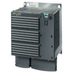
- Variable Frequency Drives (VFDs)
For example, in a conveyor system, a PLC can receive a signal from a sensor when a product reaches a particular position. It then processes the control logic and activates a motor, stopper, or alarm as required.
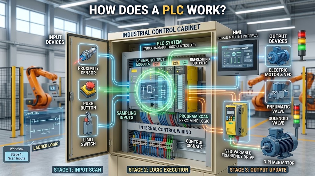
How Does a PLC Work?
A PLC normally operates in a continuous cycle called the scan cycle. During each cycle, it reads input conditions, executes its control program, and updates the outputs. The exact sequence and timing depend on the PLC model, configuration, and program.
①
Read InputsRead sensor and switch states.
②
Execute LogicEvaluate program instructions.
③
Update OutputsUpdate outputs according to the program.
④
CommunicationExchange data with connected systems when configured.
The scan cycle repeats continuously while the PLC is running. Its scan time depends on factors such as program size, CPU performance, communications, and hardware configuration. Some PLCs also support interrupts, periodic tasks, and other execution modes.
Practical example: In an automatic water tank system, a level sensor provides information to the PLC. The PLC evaluates the level conditions and controls a pump according to the programmed start and stop logic.
Main Components of a PLC System
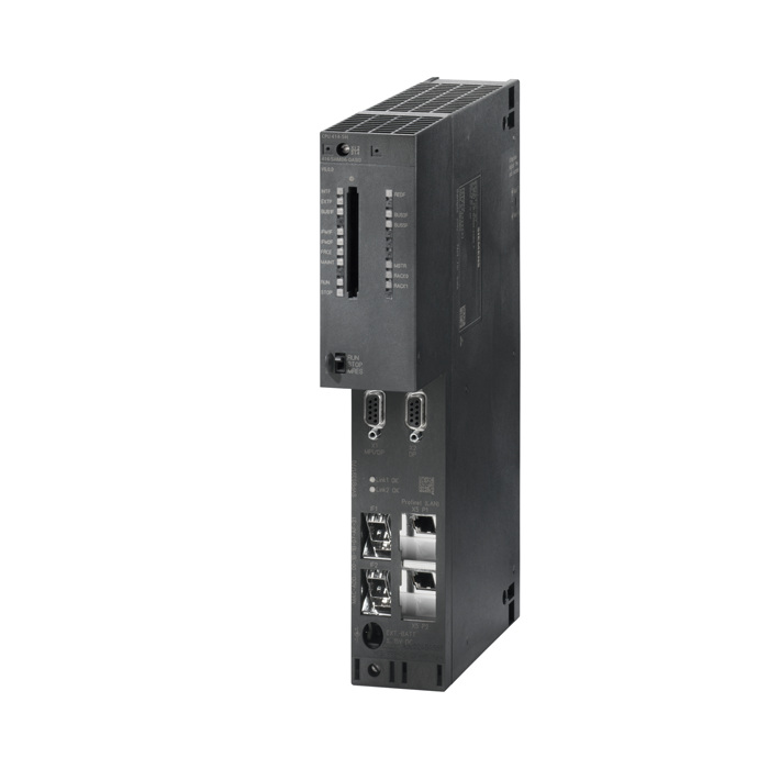
A typical PLC automation system consists of several hardware and software components that work together to monitor and control an industrial process.
1. CPU
The Central Processing Unit executes the control program, processes data, and manages PLC operations.
2. Power Supply
Provides the required electrical power to the PLC and its supported modules.
3. Input Modules
Receive signals from switches, sensors, transmitters, and other field devices.
4. Output Modules
Send control signals to relays, contactors, valves, indicators, and compatible equipment.
5. Communication Interface
Enables data exchange with HMIs, SCADA systems, remote I/O, drives, and other controllers.
6. Programming Software
Allows engineers to develop, test, monitor, and troubleshoot PLC programs.
Depending on the application, a PLC system may also include analog modules, safety modules, remote I/O, memory cards, communication processors, and expansion racks.
What Is PLC Programming?
PLC programming is the process of creating instructions that tell a programmable logic controller how to monitor inputs and control outputs. Engineers use programming software to develop logic for machines, production lines, and industrial processes.
A PLC program may control motor start and stop sequences, conveyor interlocks, tank filling, temperature regulation, alarm handling, or communication with a Variable Frequency Drive (VFD).
Example: Motor Start and Stop Logic
A simple motor control sequence may follow these conditions:
- Pressing the Start button requests the motor to run.
- Pressing the Stop button stops the motor.
- An overload or fault condition prevents or interrupts operation.
- An interlock prevents starting when required conditions are not satisfied.
Important: Real motor control must include appropriate electrical protection, interlocks, and risk-assessed safety measures. PLC logic alone should not replace a properly designed safety system.
PLC Programming Languages Explained
IEC 61131-3 defines programming languages and related elements commonly used in programmable controller systems. The commonly referenced languages are Ladder Diagram, Function Block Diagram, Structured Text, Sequential Function Chart, and Instruction List. Instruction List was included in earlier editions and is deprecated in the 2013 edition.
| Language | Type | Typical Use |
|---|---|---|
| Ladder Diagram (LD) | Graphical | Discrete control, interlocks, and maintenance troubleshooting |
| Function Block Diagram (FBD) | Graphical | Signal processing, control loops, and reusable function blocks |
| Structured Text (ST) | Textual | Calculations, data handling, and complex algorithms |
| Sequential Function Chart (SFC) | Graphical sequencing method | Step-by-step machine and process sequences |
| Instruction List (IL) | Textual, legacy | Older PLC projects; not a recommended choice for new IEC 61131-3 projects |
Note: Not every PLC manufacturer or model supports every language. Available languages depend on the controller, programming environment, and applicable standard edition.
1. Ladder Diagram (LD)
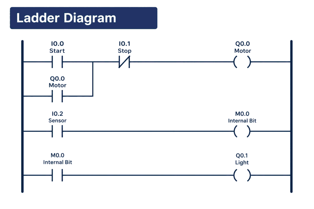
Ladder Diagram is a graphical PLC programming language that resembles traditional relay logic diagrams. It is widely used in industrial automation because electricians, technicians, and engineers can often understand its contacts, coils, and logic branches quickly.
Basic Ladder Logic Example
The following simplified example illustrates a normally open Start contact controlling a Motor_Run coil.
 L1                                      L2
 |                                        |
 |--------[ Start_PB ]--------( Motor_Run )|
 |                                        |
This is a conceptual illustration, not a complete motor control circuit. A real start/stop circuit may require seal-in logic, stop conditions, overload feedback, permissives, and appropriate safety measures.
Advantages of Ladder Diagram
- Easy to follow for many discrete-control applications.
- Convenient for online monitoring and troubleshooting.
- Well suited to interlocks, timers, counters, and motor control.
- Supported by many major PLC platforms.
Ladder Diagram is often a good starting point for beginners learning industrial PLC programming.
2. Function Block Diagram (FBD)
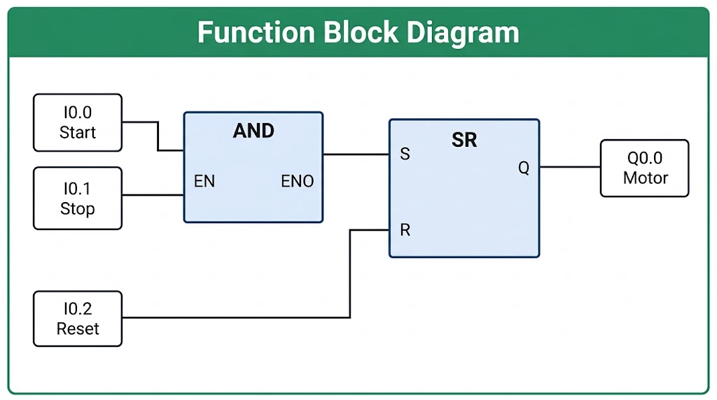
Function Block Diagram represents control logic using interconnected blocks. Each block performs a specific function, such as comparison, timing, arithmetic, scaling, or PID control.
Simplified FBD Example
The example below shows a conceptual signal flow from an input through a processing block to an output.
Input
Sensor_Value
→
Function Block
Compare / Scale
→
Output
Control_Signal
Advantages of FBD
- Clearly shows relationships between signals and functions.
- Useful for analog signal processing and control loops.
- Encourages reusable and modular control logic.
- Can make complex calculations easier to organize visually.
FBD is particularly useful when a control application involves multiple connected functions or continuous process variables.
3. Structured Text (ST)
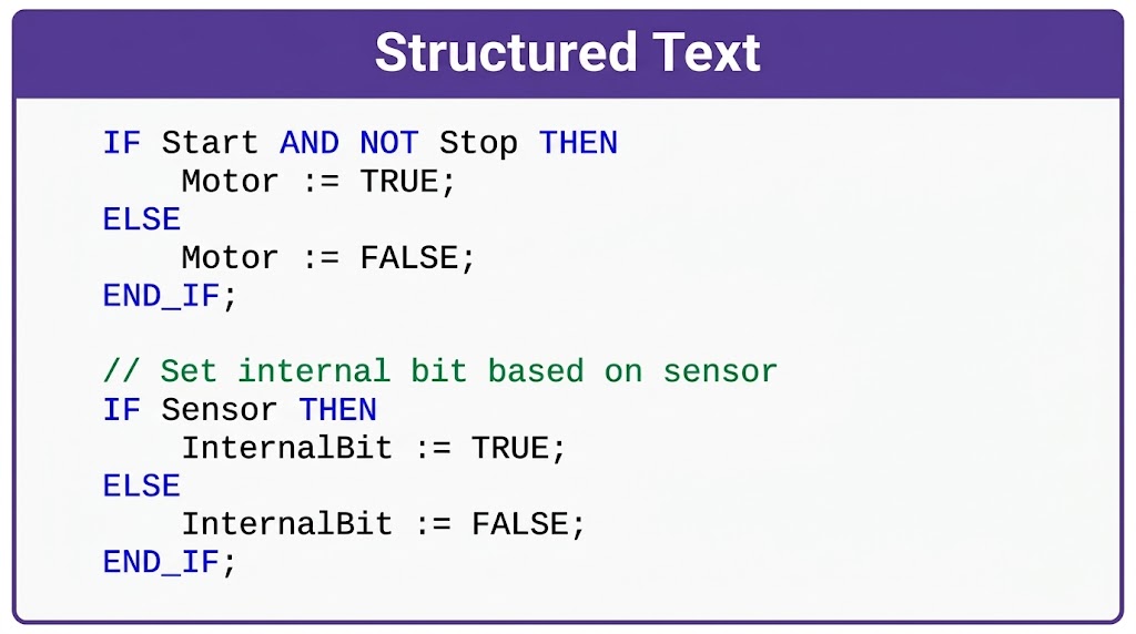
Structured Text is a high-level textual PLC programming language with syntax similar to languages such as Pascal. It is useful for mathematical calculations, conditional logic, loops, data processing, and algorithms.
Structured Text Example
The following illustrative IEC-style example compares a tank level with a threshold.
IF Tank_Level >= 80.0 THEN
    High_Level_Alarm := TRUE;
ELSE
    High_Level_Alarm := FALSE;
END_IF;
In this example, the alarm variable becomes TRUE when the tank level reaches or exceeds 80.0. The actual data types, units, I/O mapping, and alarm behavior must be configured for the application.
Advantages of Structured Text
- Efficient for calculations and complex conditions.
- Suitable for arrays, loops, and structured data processing.
- Can reduce repetitive logic in suitable applications.
- Useful when implementing reusable algorithms.
Structured Text is a valuable language to learn after understanding basic PLC logic, particularly for advanced automation and data-oriented tasks.
4. Sequential Function Chart (SFC)
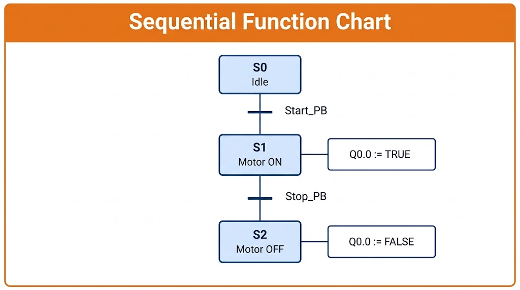
Sequential Function Chart is used to organize control processes into steps and transitions. It is especially useful when a machine must follow a defined sequence of operations.
SFC Sequence Example
Step 1: Idle
Wait for Start Command
↓
Transition
Start Condition Met
↓
Step 2: Operate
Run the Required Operation
↓
Transition
Operation Complete
↓
Step 3: Complete
Stop or Return to Idle
This simplified sequence could represent a packaging, material-handling, or machine operating cycle. Actual SFC projects require appropriate step actions, transition conditions, fault handling, and restart behavior.
Advantages of SFC
- Makes multi-step sequences easier to understand.
- Separates operating steps from transition conditions.
- Helps organize machine states and process stages.
- Supports clearer troubleshooting of sequence-related faults.
Which PLC Programming Language Is Best?
There is no single PLC programming language that is best for every application. The right choice depends on the control task, available PLC software, maintenance team’s experience, and project standards. Many industrial projects combine more than one language.
| Requirement | Suitable Starting Point |
|---|---|
| Motor start/stop and interlocks | Ladder Diagram |
| Signal processing and function connections | Function Block Diagram |
| Complex calculations and data handling | Structured Text |
| Multi-step machine sequences | Sequential Function Chart |
| Older systems using legacy code | Maintain the existing language where appropriate and supported |
Recommendation for beginners: Start with Ladder Diagram to understand contacts, coils, timers, counters, and interlocks. Then learn Function Block Diagram and Structured Text to expand your ability to handle analog controls and more complex logic.
Major PLC Manufacturers and Programming Software
Several manufacturers supply PLCs and automation platforms for industrial applications. Their programming tools, hardware ranges, supported languages, and communication options vary by product family.
| Manufacturer | Example Platform / Software | Common Use |
|---|---|---|
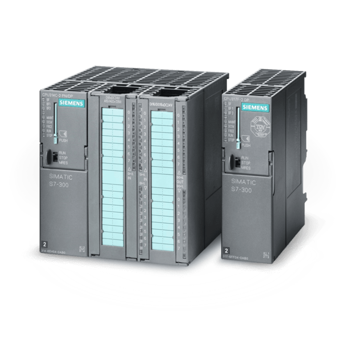
| Siemens | SIMATIC S7; TIA Portal | Manufacturing and process automation |
| Mitsubishi Electric | MELSEC; GX Works | Machine and factory automation |
| Rockwell Automation | ControlLogix / CompactLogix; Studio 5000 | Manufacturing and process control |
| Omron | NJ / NX; Sysmac Studio | Machine automation and motion control |
| Schneider Electric | Modicon; EcoStruxure Control Expert | Industrial and process automation |
| ABB | AC500; Automation Builder | Machine and industrial automation |
| Beckhoff | TwinCAT | PC-based control and motion systems |
| Delta | ISPSoft / DIAStudio, depending on product | Machine and factory automation |
Always check the manufacturer’s documentation for compatibility, supported languages, firmware requirements, and the correct software version for your PLC model.
PLC Applications in Industrial Automation
PLCs are used across many industries because they provide reliable, programmable control for machines and processes.
Manufacturing
Controls assembly lines, conveyors, packaging machines, and automated workstations.
Steel and Metal Processing
Coordinates interlocks, material handling, auxiliary equipment, and selected machine sequences.
Water Treatment
Monitors tank levels, pump sequences, valve positions, and alarms.
Power and Utilities
Supports auxiliary control, status monitoring, and equipment interlocking where appropriate.
Food and Beverage
Automates filling, mixing, conveying, batching, and packaging processes.
HVAC and Building Systems
Manages selected pumps, fans, dampers, temperature controls, and equipment status.
In larger facilities, PLCs may communicate with Human-Machine Interfaces (HMIs), SCADA systems, drives, and plant-level networks to provide operators with process visibility and control.
Advantages and Limitations of PLCs
Advantages
- Designed for industrial control environments.
- Logic can be modified without rewiring an entire relay system.
- Supports monitoring and troubleshooting tools.
- Can integrate with HMIs, drives, sensors, and networks.
- Offers modular expansion on supported platforms.
- Enables repeatable and consistent machine operation.
Limitations
- Hardware, licenses, and specialized software can be costly.
- Advanced programming requires training and experience.
- Vendor-specific platforms may require different skills.
- Networked systems need suitable cybersecurity measures.
- Complex processes may require distributed or dedicated control architectures.
Selecting the right PLC requires evaluating I/O requirements, processing performance, communication protocols, environmental conditions, safety requirements, expandability, and long-term support.
PLC Programming Best Practices
Well-organized PLC programs are easier to understand, test, maintain, and troubleshoot. Following consistent engineering practices can reduce downtime and improve the reliability of industrial automation systems.
1
Use meaningful tag names
Choose descriptive names such as Conveyor_Motor_Run or Tank_Level_High rather than unclear abbreviations.
2
Organize the program into logical sections
Separate functions such as motor control, alarms, sequences, analog processing, and communications where the platform supports it.
3
Document important logic
Add comments explaining process conditions, interlocks, unusual calculations, and important operating assumptions.
4
Test before commissioning
Use simulation or a test environment where available. Verify normal operation, fault cases, limits, and recovery behavior before production use.
5
Maintain backups and version control
Keep approved backups, document changes, and ensure the correct project version is available for recovery.
6
Treat safety and cybersecurity seriously
Use suitable safety-rated systems where required, restrict unauthorized access, and follow site change-management procedures.
How to Learn PLC Programming
Learning PLC programming is easier when you combine basic electrical knowledge, programming concepts, simulation, and practical troubleshooting. Beginners can follow a structured learning path.
Step 1: Learn the fundamentals
Understand digital and analog signals, relays, contactors, sensors, electrical diagrams, and basic control circuits.
Step 2: Start with Ladder Diagram
Practice contacts, coils, set/reset instructions, timers, counters, interlocks, and motor-control logic.
Step 3: Learn a real PLC platform
Choose a platform based on the equipment available to you, such as Siemens TIA Portal, Rockwell Studio 5000, or another supported environment.
Step 4: Practice with simulation
Build small projects such as traffic-light sequences, tank-level control, conveyor logic, and alarm handling using appropriate simulation tools.
Step 5: Expand your skills
Learn analog signals, PID control, HMI design, VFD communication, industrial networks, Structured Text, and troubleshooting methods.
Practice regularly and document each project. Working through small, realistic problems builds stronger skills than memorizing programming instructions alone.
Frequently Asked Questions About PLC Programming
1. What is the easiest PLC programming language to learn?
Ladder Diagram is often a good starting point because its visual structure resembles relay logic. The best language depends on your experience and the application.
2. How many PLC programming languages are there?
IEC 61131-3 is commonly associated with five languages: LD, FBD, ST, SFC, and IL. Instruction List was included in older editions and is deprecated in the 2013 edition.
3. Is PLC programming difficult?
Basic PLC programming can be learned through regular practice. More advanced applications involving motion, process control, networking, safety, and complex sequences require additional knowledge and experience.
4. Which software is used for PLC programming?
The software depends on the PLC manufacturer and model. Examples include Siemens TIA Portal, Rockwell Studio 5000, Mitsubishi GX Works, Omron Sysmac Studio, and Schneider Electric EcoStruxure Control Expert.
5. Can different PLC programming languages be used in one project?
Yes. Many platforms allow supported languages to be combined within a project. The exact options depend on the PLC, programming software, and project architecture.
6. What is the difference between a PLC and an HMI?
A PLC executes control logic and manages connected equipment. An HMI provides a graphical interface for operators to view process information, acknowledge alarms, and issue authorized commands.
7. What is the difference between a PLC and SCADA?
A PLC usually performs local machine or process control. SCADA is a supervisory system that can collect data, display trends and alarms, and enable authorized operators to monitor or control processes across a larger system.
8. Can I learn PLC programming without owning a PLC?
Yes. Depending on the platform, programming software, simulators, and virtual controllers can help you practice basic logic without purchasing physical hardware. Check the relevant software’s licensing and system requirements.
Conclusion
Programmable Logic Controllers are a fundamental part of modern industrial automation. They help control machines, coordinate production processes, monitor field signals, and support reliable equipment operation.
Understanding the main PLC programming languages—Ladder Diagram, Function Block Diagram, Structured Text, and Sequential Function Chart—helps engineers choose an appropriate approach for different automation tasks. By combining programming knowledge with electrical fundamentals, systematic testing, and troubleshooting skills, beginners can build a strong foundation in industrial control.
Industrial Automation Products from Unique International
Unique International supplies industrial automation and electrical equipment for industrial applications in Bangladesh. Our product range includes PLCs, HMIs, Variable Frequency Drives (VFDs), servo systems, stepper systems, sensors, actuators, valves, and industrial spare parts from leading manufacturers.
If you need automation equipment or replacement parts for your facility, contact our team to discuss your requirements and request a quotation.